
The Azimuth Scope Kit provides quick, easy azimuth solutions for a wide range of elevated antennas, including tower- and building-mounted installations, from ground level. It is suitable for measuring actual azimuth only.
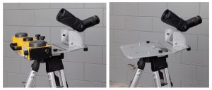 Azimuth Scope Kit (with and without AAT)
Instructions for Use
1. Secure the Azimuth Scope Kit to a Tripod
2. Position tripod by extending and locking the legs.
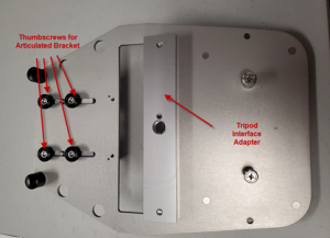 3. Attach the Tripod Interface Adapter to the Mount Baseplate using the two thumbscrews
4. Screw azimuth scope adapter to the tripod using the attachment knob on the tripod.
5. Attach the articulated bracket to the Mount Baseplate by using the 4 threaded knobs from underneath the Mount Baseplate.
6. Attach the scope to the Articulated Bracket by aligning the alignment dowel in the bottom of the scope to the correct hole in the mount and then use the thumbscrew to secure scope to bracket.
7. Attach AAT to mount with handle facing away from the scope and tighten thumbscrews to secure AAT to mount.
8. Remove the protective caps on scope.
There are 3 methods for using the AAT Azimuth Scope Kit. The choice of method will be determined by the situation in the field. There are two methods for using the kit when facing the antenna – i.e., viewing the antenna “head-on”. If viewing the face of the antenna is not practical, then the third method – looking across the back of the antenna (90 degrees to the face of the antenna) may be used. The following paragraphs describe each method. Note that the methods are described in order of preference.
Method 1 – Measure azimuth from the antenna face using the antenna’s bottom plate and the mast pipe.
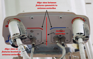
1. Set the tripod with the scope, and AAT attached a sufficient distance away from the tower, building, or other structure to permit a good view of the antenna and the mounting structure behind it (mast pipe). A good rule of thumb is 150 feet minimum, or 1 foot away for every 1 foot of height of the antenna. Note that these distances are guidelines and good results may be obtained at lesser distances by experienced crews.
2. Remove the scope from the articulated based and using the lowest magnification, locate the antenna and visually align the points to be measured in the viewfinder by safely walking to the left or right while viewing the points. The user must be able to see both the bottom plate of the antenna and the mounting pipe where the antenna mounting brackets are attached. Once the approximate antenna centerline has been determined using the scope in hand by visually aligning the chosen alignment points, place the tripod and azimuth kit in that location on the ground, reattach the scope to the articulated based, and adjust/move the AAT with scope and tripod together to align the antenna centerline with the centerline of the antenna mounting pipe by viewing the points through the scope eyepiece. This will require physically moving the AAT, scope, and tripod unit to bring them in line.
3. When the mast pipe, the centerline of the antenna bottom plate and the AAT w/scope are in line continue with the section entitled MEASURING AND CAPTURING AZIMUTH FROM THE GROUND below.
Method 2 – Measuring azimuth from using the face of the antenna
 1. Set the AAT with the scope and tripod attached a sufficient distance away from the tower, building or other structure to permit a good view of the antenna and the mounting structure behind it (mast pipe). A good rule of thumb is 150 feet minimum, or 1 foot away for every 1 foot of height of the antenna. Note that these distances are guidelines and good results may be obtained at lesser distances by experienced crews.
2. Remove the scope from the articulated based and using the lowest magnification, locate the antenna and visually align the points to be measured in the viewfinder by safely walking to the left or right while viewing the points. This will determine the approximate location for the tripod. See Figures 2-6 and 2-7 below. The idea is that if the sides or edges of the antenna look the same, the user is directly in front of the antenna. This approach is similar to how magnetic compasses have traditionally been used to measure azimuth, but much more precise and repeatable.
3. Place the tripod at the determined location and reattach the scope to the articulated brace.
4. Reattach the scope to the articulated brace.
5. Locate the antenna to be measured in the viewfinder.
6. View the antenna face and move the AAT, azimuth scope, tripod assembly from side to side to make the two sides of the antenna look the same when viewed through the scope.
7. When the two sides of the antenna appear equal in the view finder, continue with the section entitled MEASURING AND CAPTURING AZIMUTH FROM THE GROUND below.
Method 3 – Measuring Antenna Azimuth from the Side of the Antenna
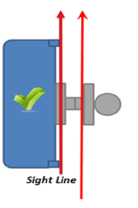 1. Antenna azimuth can also be accurately measured from the side of the antenna using the AAT with scope and tripod on the ground. As with the direct frontal measurements, the AAT must not be positioned under or nearly under the antenna.
2. Set the AAT with the scope and tripod attached a sufficient distance away from the tower, building or other structure to permit a good view of the side and back edge of the antenna. A good rule of thumb is 150 feet minimum, or 1 foot away for every 1 foot of height of the antenna. Note that these distances are guidelines and good results may be obtained at lesser distances by experienced crews.
3. Remove the scope from the articulated based and using the lowest magnification, locate the antenna and visually align the points along the back of the antenna to be measured by safely walking left and right to obtain the alignment. This will determine the approximate location for the tripod.
4. Place the tripod at the determined location and reattach the scope to the articulated brace.
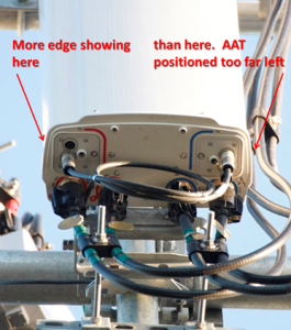
5. Using the scope, align the AAT so it is measuring directly across the back of the antenna. Positioning the AAT too far towards the front of the antenna will block the view of the far edge of the antenna. Positioning the AAT too far in the opposite direction will expose some of the back side of the antenna in the view which is an indicator of incorrect alignment. See Figure 3-1.
6. When the back of the antenna is in line with the scope view, continue with the section entitled MEASURING AND CAPTURING AZIMUTH FROM THE GROUND below.
MEASURING AND CAPTURING AZIMUTH FROM THE GROUND
1. With the antenna properly located in the scope viewfinder using one of the three methods above, adjust the magnification such that the side and antenna lower edge are easily viewed. Adjust the position of the AAT/scope/tripod assembly as necessary.
2. Connect to the AAT in the standard way by powering on the AAT and connecting using WiFi or USB-C cable (see Quick Start Guide for detailed instructions). The WiFi connection can be made using the Android App (preferred) or by using WiFi and a browser.
3. On the AAT Measure page, set the proper AAT Orientation and click Apply.
i. “AAT Faces Left” if measuring from the right of the antenna.
ii. “AAT Faces Right” if measuring from the left side of the antenna.
iii. “AAT Faces Back” if measuring from in front of the antenna.
iv. If the measured azimuth is 180 degrees opposite of expected, the orientation is likely incorrectly set.
4. Ensure that the AAT is within +/- 1 degree of level in both tilt and roll. Adjust the tripod leg height as necessary to obtain acceptable tilt and roll values.
5. Verify the antenna position through the viewfinder, ensuring that the scope is still aligned to the antenna as required
6. Capture Alignments in the standard way using the AAT
7. After initial capture, the user should review results and then save or reject.